Gas-source reading
Temperature, mass flow, composition and dust load define the first engineering boundary.
Waste-heat recovery boiler
A horizontal firetube recovery boiler calculated project by project for exhaust-gas flow, temperature, pressure target and plant constraints, with configurations from recovery-only to combined burner-recovery operation.
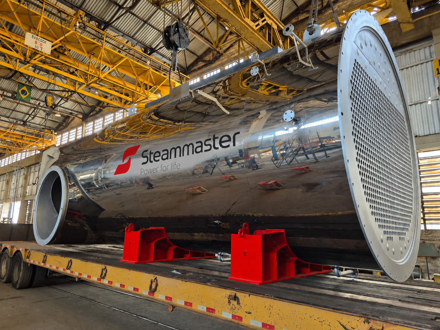
The CRS/CRP architecture uses a cylindrical vessel with tube sheets at both ends and a firetube bundle inside the shell. Tube number, diameter and length are calculated from the thermal balance and pressure drop that the process can accept.
Temperature, mass flow, composition and dust load define the first engineering boundary.
Pressure, saturation condition and demand profile guide shell volume, tube bundle and control strategy.
Layout, access, economizer position and downstream stack logic must be read together.
Each CRS is individually calculated before the final machine is frozen for fabrication.
Next engineering step
For a first CRS reading, the useful package is gas temperature, flow, composition, available pressure drop, desired steam pressure, expected production, operating hours, footprint, maintenance access and whether auxiliary firing or multiple gas streams are required.